NOTE Open Nixie Project
Gas filling manifold
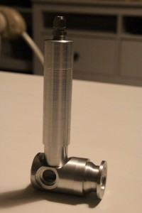
Farny started building his own gas filling manifold as the previous solutions he found weren’t satisfactory. Farny says the manifold should have the following features:
- All parts should be brazed together with an aluminum-silicon (AlSi) compound
- KF-25 flange connection
- Baratron connection
- Evacuation tube connection
- Valve for fine control of neon
- Valve for fine control of argon
- Valve for fine control of vacuum - when the pressure in the system is too high, this will suck some gas back. This way it won’t be necessary to evacuate the whole system and start filling from scratch.
All the parts for Farny’s gas filling manifold were machined on his metal lathe, using a chuck with 4 independent jaws.
The base of the manifold has one hole for the baratron, and one for the evacuation tube. All holes are 15mm in diameter to keep pumping as fast as possible.
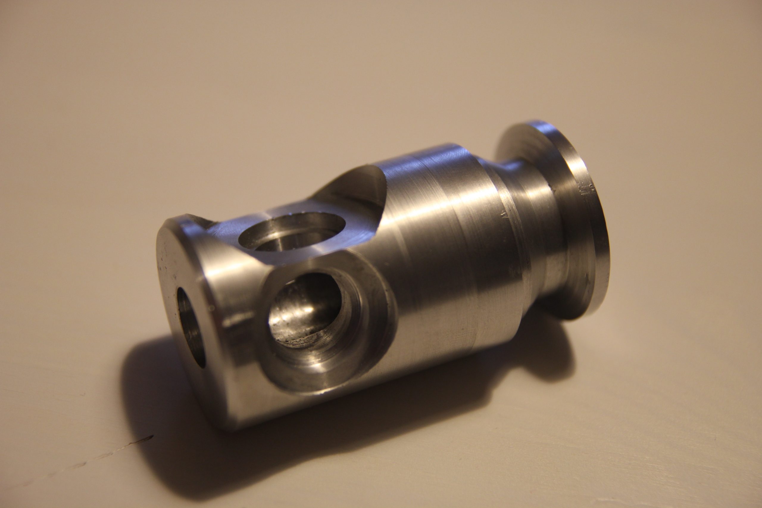
The below image shows the KF-25 flange.
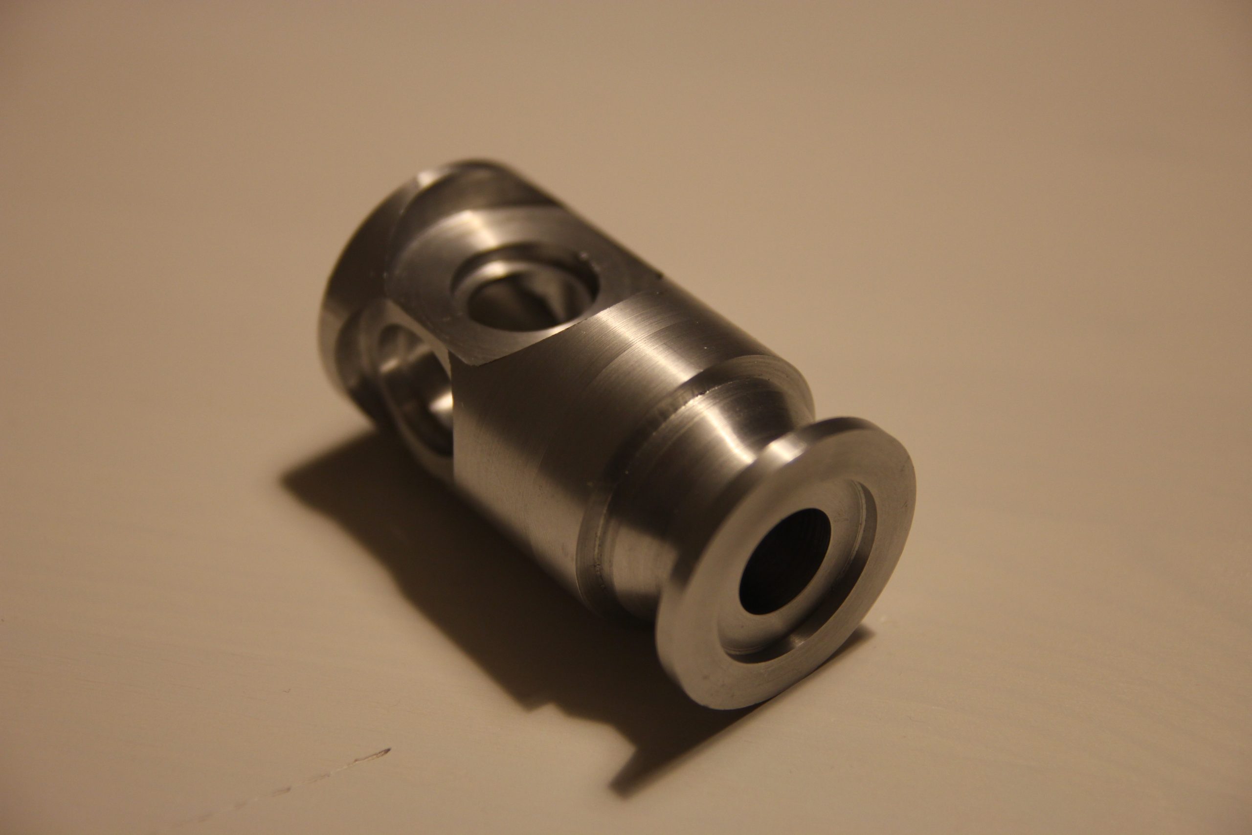
The baratron connection will be brazed to the manifold as shown below.
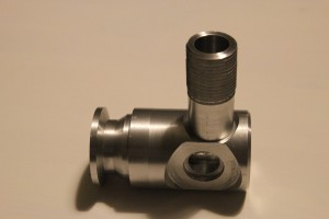
Next is the evacuation pipe with a fitting for a 6mm glass tube, I believe that when manufacturing the long glass tube will be sealed with glass working.